
Sutro Tunnel Air Shafts

by Bob Thomasson 17 November 2020, Revised 20 November 2024
Adolph Sutro planned 4 air shafts, spaced along the Sutro Tunnel route and numbered Air Shaft 1 through 4, beginning at the tunnel portal. Another air shaft, called simply Air Shaft, was constructed 2,225 feet from the portal, between the portal and Air Shaft 1. This unnumbered air shaft may have been an unplanned necessity to ventilate the initial tunnel workings or it may have allowed drifting along the tunnel route, allowing for rapid initial progress. I’ll arbitrarily call it Air Shaft 1A. Greg Hess also drilled a ventilation well for Houston Oil and Minerals during their 1980’s attempt to re-open the tunnel. The ventilation well may be near the location of Air Shaft 1A.
The Sutro Tunnel was a major engineering effort and the air shafts were engineering achievements in their own right. One purpose of the air shafts was to provide ventilation over the roughly 3.8 mile main tunnel length. However, according to the November 1872 Report of the Superintendent of the Sutro Tunnel Company (Adolph Sutro himself was the Superintendent), the shafts had an additional purpose: allowing tunnel work to be conducted in both directions from the bottom of the shafts.
Sutro hired excellent engineers, including Hermann Schussler, the chief engineer of the Marlette Lake Water System, to survey the air shaft locations and supervise construction. Other notable engineers on the project included Arthur DeWitt Foote and Danish engineer, Carl O. Wederkinch (sometimes spelled Wedekind and confused with German miner George Wedekind). All of the tunnel engineers came from illustrious backgrounds and went on to further success after leaving the tunnel project.
The tunnel surveying was incredibly accurate over the rough hilly terrain and allowed the shafts to be sunk directly over the tunnel route and to the exact tunnel depth far ahead of tunnel construction.
Sinking the air shafts before the tunnel reached the air shaft locations would allow the tunnel construction to proceed in two directions from the bottom of each shaft. Tunnel work could progress from a total of 9 points of attack: from either direction from the bottom of each shaft and from the tunnel portal. This technique of working from two directions from a central shaft was previously used by Sutro’s engineer, Carl Wederkinch, at the Hoosac Tunnel in Massachusetts.
Unfortunately, problems stymied the plan to drive the tunnel in two directions from the bottom of each of the 4 air shafts. Air Shafts 3 and 4 were never completed due to encountering more groundwater than the available pumps could handle. The tunnel was driven from the bottom of Air Shaft 2, but this work was accompanied by great drama, to be described later. During all or part of the tunnel construction Sutro was also limited by the terms of his funding. He was limited to a rigid monthly expenditure of $24,000 and the expense of extra crews and equipment at the bottom of each air shaft would have greatly exceeded his monthly budget. If the tunnel construction could have proceeded from the planned nine different points, the tunnel would have been completed years earlier and the Sutro Tunnel story we know today may have been very different.
Sutro hoped that he could finance some of the tunnel work with ore discovered along the tunnel path and air shaft workings. According to Richard Garner “The Economic History of a Mining Bonanza,” the tunnel passed through the following lodes; the Great Flowery Lode near Shaft 1, the Coryell Lode between Shafts 1 and 2, the Occidental Lode just beyond the Coryell Lode and the Sulferino Lode between Shafts 3 and 4.
St. John’s Mine is on the Occidental Lode, located just south of Air Shaft 3, and there are reports of a drift from the tunnel to the mine and the Sutro Tunnel 1884 Annual Report shows a tiny Saint John’s Mine royalty payment of $44. There was an assay lab located near the tunnel portal and the Nevada State Historical Society Research Library has bound copies of assays done during the tunnel and shaft construction. It appears that little profitable ore was found along the tunnel route, or possibly the main priority was to get the tunnel completed with mining work considered a distraction to come later.
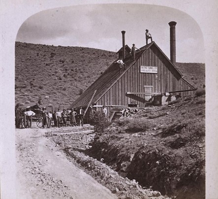
Following are comments and also selected excerpts in bold font from the 1872 Report to the Superintendent describing the general air shaft construction and infrastructure:
—Frame building, 16 by 32 feet, 18—foot posts, suitably constructed for the protection of machinery; containing an engine and boiler.
Timbering of Shafts
Over each of the shafts there is erected a hoisting frame, carrying the pulley for wire ropes for hoisting from sinking shaft, and for hoisting and lowering machinery through pump shaft. The shafts are timbered with timber 10” by 12”, 10” by 14”, and 10” by 10”, in the following manner: 10” by 12” horizontal wall timbers, with 10” by 14” center or division girt, the sets of frames placed 5 feet from center of the central timber, with 10’’ by 10” posts placed vertically in each corner and in center of side walls, the whole backed or lagged with 2 by 12 inch plank, and lined with 1 x 12 inch boards on inside.
The pump division is furnished with platforms or landings at each 15 feet, vertically, with ladders connecting them, forming safe passageway to or from the bottom of the shaft or either of the pumps or machinery.
Timber contained in Timbering of Shafts
Each 100 feet of shaft requires 28,446 feet of lumber; each pump station with tanks complete requires 17,440 feet. There is now completed at the different shafts the following number of stations and tanks complete: At Shaft No. 1 one station and tank complete; at Shaft No. 2 two stations and tanks complete; at Shaft No. 3 one station and tank complete; at Shaft No. 4 one station and tank complete. The first stations are made 275 to 300 feet below the collar of the shafts. The above is about the distance between pump stations from collar of shafts to the level of the tunnel.
Air Shaft No. 1.
This shaft is located 4,915 feet from the portal and reached the tunnel depth at 523 feet. Water originating at shaft 3 was delivered to a reservoir at the divide between shafts 1 and 2. From there it was piped to another reservoir near shaft 1 and water pumped from shaft 1 was also added to the reservoir. Water stored in the shaft 1 reservoir was then piped down shaft 1 where the pressure due to the 500+ foot elevation head was was used to power a water turbine at the tunnel portal. This water turbine may have been the Leffel Turbine that was installed below grade at the machine shop. Sutro also proposed installing a 50 foot diameter water wheel at the portal but it is doubtful that it was ever installed. The performance of the machine shop turbine was limited due to less than anticipated water flow during tunnel construction when the tunnel had not yet started draining the Comstock mines.
The final destination of the Leffel turbine is not known, possibly it is still in the ground 60 feet below the Machine Shop site.
More excerpts from the Report of the Superintendent:
“Frame building, heavy timber; hoisting and engine room, 36 by 96 feet, 18-foot posts, with elevation over shaft 18 feet above main building. Hoisting frame 14 by 30 feet, with two wings attached for boiler room and carpenter shop, 36 by 40 feet each, with ventilator over engine boiler and hoisting rooms, with miners’ changing room over boiler 11 by 40 feet, 8 feet high. The above-named building is constructed in the most substantial manner, with truss roof throughout.
In connection with the above works there are two (2) water-tanks for safety against fire, 14 by 16 feet, 8 feet deep. Also one hot-water tank 6 by 10 feet, 6 feet deep, for supplying boiler. And also three store-rooms in the above-described building, one for miners, one for engineers, and one for carpenters.
Boarding-house, Shaft No.1 – Frame building, 20 by 40 feet, 2 stories in height, suitably constructed for convenience, and used for a boarding and lodging-house, with an addition thereto 12 by 30 feet, used for kitchen, store-room &c.
Lodging-House, Shaft No.1 – Frame building 14 by 20 feet, conveniently constructed and used for a lodging-house.
Office and Room for Foreman at Shaft No. 1—Frame building 14 by 20 feet, conveniently constructed, and used for an office and room for foreman.
Blacksmith Shop, Shaft No.1 ——Frame building 18 by 20 feet, with suitable appurtenances, and used as a blacksmith shop. And also a charcoal house 18 by 24 feet, suitable for storing charcoal.”
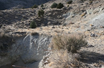
Each air shaft construction site was similar to a small mining camp, complete with a boarding house for workers and it’s surprising how very little is left at each site. I did not find the typical rusty can trash dumps usually found very near to old mines. Possibly the tunnel company was very particular about keeping the sites cleaned up so that they could proudly show the sites to important visitors. Also, materials and equipment were likely immediately salvaged for use elsewhere or sold once they were no longer needed for air shaft construction..
Air Shaft 1 was the scene of considerable drama in January, 1961. Three Reno High School students came to Sutro to explore the tunnel, looking for artifacts for a school history class. Discovering that the tunnel entrance was closed, they decided to see if they could enter the tunnel through Air Shaft 1. Flipping a coin to see who would go down the shaft first, Larry Dacek was lowered down the shaft on a rope. Not far down, the rope broke and Larry fell to a shaky ledge, probably one of the pump work stations, supported by rotten timbers. He was injured but conscious and one of his friends stayed to talk to him while the other went for help. Walt German, an off-duty Carson City police officer, heroically went down the shaft and rescued Dacek after he had been trapped in the shaft for 11 hours. Today, the shaft is collapsed and only a shallow pit remains.
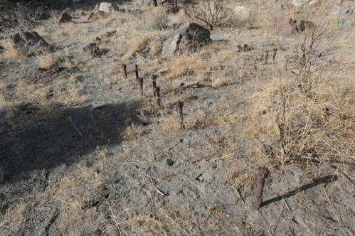
These may be the anchor bolts that held the hoist in the previous photo. Interesting that someone took the time to carefully replace the nuts after removing the machinery.


Air Shaft No 2
This air shaft is located 9,020 feet from the tunnel portal and reached the tunnel at a depth of 1,041 feet.
Frame buildings, heavy timber, substantially erected, as follows, to wit: Hoisting-room, boiler-room, engine-room, tanks, carpenter shop, changing-room, boarding-house, lodging-house, office and room for foreman, blacksmith’ shop, charcoal house; all of precisely the same dimensions as at Shaft No. 1, as above given. And also one hard- coal dump 20 by 40 feet, 12 foot posts.
Renowned civil engineer Arthur DeWint Foote was responsible for Air Shaft 2 construction and Sutro fired him after Foote struck an overwhelming flood of water that delayed work. The collision with Sutro did not damage Foote’s career as he went on to numerous achievements. Here is Foote’s explanation from “Interviews with Mining Engineers” by Thomas Arthur Rickard, 1922:
We had to run the pumps so fast that the steam-pipe heated the shaft until it became impossible for men to work. Sutro came to the office, fuming and swearing, whereupon I told him that we had not been ‘drowned out’ but we had been ‘burned out’. He did not like it, so we parted company.
I did not then know that he had put in the steam-pumps against the advice of everybody who understood the subject, because he could buy them for stock in the tunnel company. At that time the only kind of pump that would have served our purpose was the Cornish pump. Today, of course, under similar circumstances, we would have used electric pumps. It might be worth while, as a matter of record, to mention that while at the tunnel I helped J. B. Pitchford, who was master mechanic, put up the first air-compressor installed in the West. In fact, there had been but two in the whole country before that: one at the Hoosac tunnel and one at a Delaware & Lackawanna railroad tunnel.
The above is a good example of the never ending conflict between financing and engineering. Sutro faced the difficult and nearly decade long task of finding ways of paying for the tunnel work and necessary machinery and made compromises that he felt were necessary. The engineers had to deal with the day to day nuts and bolts repercussions of the financial decisions and it did not always end well. Nothing seems to have changed much in the ensuing 150 years.
There were more adventures related to water and Air Shaft 2. Here is an article from a 1984 issue of The Engineering and Mining Journal:
The Tapping of Shaft No. 2, Sutro Tunnel. From the Virginia City Enterprise. THE tapping of the water in Shaft No. 2, Sutro Tunnel, was yesterday successfully accomplished, under the supervision of chief engineer of the works, CARL O. WEDEKIND, a most accomplished young engineer. He had charge of the central shaft section of the Hoosac Tunnel, and has had much experience in other large works of the kind. He took charge of the tunnel as chief engineer May 1st, 1874, and has since been conducting that work.
It will be remembered that on the 30th of June, 1874, the men were driven out of shaft by the striking of a heavy body of water as they were drifting west from its bottom and the shaft, 1,040 feet in depth, was filled up to within 100 feet of its top. Work at that point was then suspended until the tunnel header should be advanced far enough to tap the immense body of water obtained in the shaft.
On the 8th inst., the regular work of driving the header of the tunnel was suspended, being at a distance of 8,800 feet from the mouth of the tunnel, 98 feet from the water in shaft No. 2. A diamond drill was mounted and adjusted by Mr. WEDEKIND, with the aid of a transit instrument for the grade, in order to exactly strike the header driven east from shaft No. 2. A double bulkhead, built of 12 – inch timbers, was constructed between the drilling machine and the face of the tunnel, with a quarter – inch boiler plate slide arranged vertically in its center.
Drilling was begun on the 9th inst. at 11 o’clock PM, the power for the drill being compressed air. It made its way through the usually hard rock at an average speed of 18 inches every 15 minutes, diameter of hole being 2 inches. Excepting one interruption of several hours, caused by the breaking of the diamond bit, the drilling went on finely, and on March 11, at 2 o’clock A. M., three times three cheers were heard from all when the drill – rod broke through.
The water coming out at the side of the rod under a head of 835 feet {360psi} (to which the water had lowered since June) was white as snow, and quite hard to feel of. Great care was taken in letting back the drill – rod, but the friction between the machine and rod and the grip of every man present was no longer sufficient. It went, like a streak of lightning, even not lacking the fiery part, and finally lodged back in the tunnel. The plate in the middle of the bulkhead went down in front of the hole, changing the 120 inches of water coming out into a beautiful white amount of feather – shaped fountain.
The idea of striking the workings of No. 2 shaft by a diamond drill through 100 feet of rock, at a distance of one and two – third miles from the mouth of the tunnel, has been doubted by almost every one. It’s successful determination establishes here the already well earned name Mr. WEDEKIND has attained by his accurate work on the Hoosac Tunnel and in other places. In three hours the water had been lowered in the shaft 128 feet. Last evening, however, we were informed that the flow had ceased. It is supposed that the drill hole is stopped up by a piece of rock, or that a stick of timber has been sucked tightly against it . The obstruction, whatever it is will doubtless be shortly removed.
The road is in reasonable shape, considering that it’s probably been 100 years since it was maintained. From the Superintendent’s report:
A large amount of grading and repairing of roads has been done by the company during the past season, one man being constantly employed upon the magnificent road constructed between Sutro and Virginia, to keep it in good condition; and it is now one of the finest highways in this part of the country.


Air Shaft 2 has a little more material laying around than the other sites; some large old cans that may have been used for machinery lubricants, some rusted iron pieces that may have been part of a steam engine or forge exhaust hood. There are also plenty of old broken bricks, which are found at all of the air shaft sites.
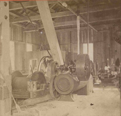
The drum shaped object hanging near the center of the photo may be a bailer, used to remove water from the shaft when the pumps were undergoing repairs.

This dam is at the mouth of the ravine below Air Dam 2, at the point where the ravine empties into 6 Mile Canyon. I don’t know if there is any connection between the dam and the water in the air shafts. There were nearby mills and the dam likely held water for powering mill machinery or for processing placer gold.

The road is in reasonable shape, considering that it’s probably been 100 years since it was maintained.
From the Superintendent’s report:
A large amount of grading and repairing of roads has been done by the company during the past season, one man being constantly employed upon the magnificent road constructed between Sutro and Virginia, to keep it in good condition; and it is now one of the finest highways in this part of the country.
Air Shaft 3
This shaft was never completed due to water flooding the shaft faster than the pumps of the time could remove it. The distance to Air Shaft 3 from the portal is 13,545 feet. The planned depth was 1,361 feet, 6 inches but water stopped the shaft work at 456 feet. Prior to the failures of Shafts 3 and 4, Mr. Sutro had predicted that drifting the tunnel from the bottoms of the air shafts would allow the tunnel to be completed by the end of 1875, about 3 years earlier than it was actually completed.
Sutro had a plan to power pneumatic drills in the tunnel with a “hurdy gurdy” water wheel, an early and inefficient water wheel that was later much improved by the Pelton Wheel. The water from Shaft 3 was pumped to the surface and diverted to a flume that took it to a reservoir at the top of the divide between Shafts 1 and 2. From the divide it was piped to a reservoir at Air Shaft 1 where it was then piped down Air Shaft 1 and evidently to a water turbine located near the tunnel portal.
From the Superintendent’s Report:
Shafts No 3 & 4. Substantial heavy frame buildings, boarding and lodging-houses and offices, at shaft No. 3 and at shaft No. 4, precisely the same as at shafts Nos. 1 and 2, as above given, with the addition at No. 3 of a stable 22 by 36 feet, suitable for eight horses, with hay-loft, grain-room, &c. Also one additional lodging house, 20 by 30 feet, conveniently arranged and used for a lodging – house.
Surprising how little evidence is left of the air shafts.
Here is an excerpt from the 1940 History of the Comstock Lode WPA Writing Project:
The St. John’s claim was located on the Brunswick Lode, in what is now included within the southern half of the Sutro Tunnel Grant. During 1872, many thousand of tons of low grade ore were quarried from the surface of the claim. The Sutro Tunnel cut the Brunswick lode in the St. John claim at a depth of 1300 feet below the surface. A south drift and supporting crosscut driven on the Sutro Tunnel level indicated the ledge to be 50feet wide. Samples taken from the ledge at that point, indicated the ore to have a value of from $4 to $5 per ton.
This could be an old abandoned section of an original road, or possibly the path of the flume carrying water from Air Shaft 3 to the divide between Shafts 1 and 2.

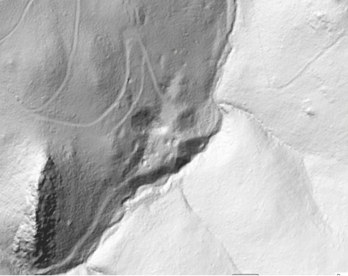
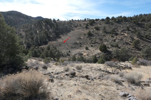
The air shaft is the small pit in the center of the image, the larger worked area below it is the Saint John’s Mine.
Air Shaft 4
Air Shaft 4 is relatively close to the Virginia City metropolitan area, so the Nevada Division of Minerals has recently fenced it in with a sturdy safety fence. All that is left of the considerable structures listed above are the foundations for the machinery with protruding bolts and scattered bricks. I believe that Mr. Sutro was very conscientious about removing and selling all equipment once it was no longer needed.
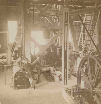
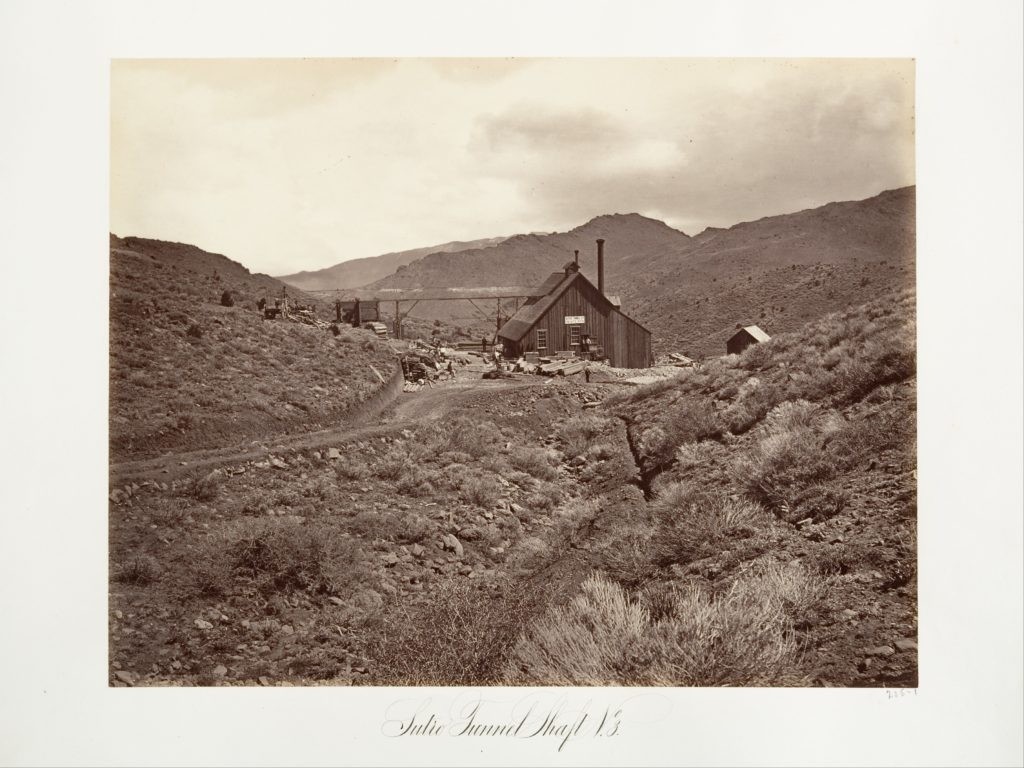
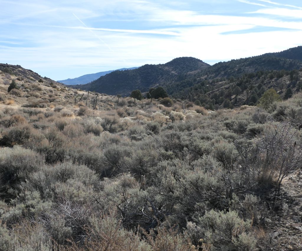
Here is how Shaft 4 looked in the 1870’s. Next to it is a photo of how it looks in 2020. Note the lack of trees in the old photo, cut down for steam engine fuel, compared to today’s picture with new growth of trees.

There is not much left, other than a fenced shallow hole in the ground and some large diameter steel bolts. Most of the time, old foundation bolts are found roughly cut off; the nuts were removed from these and the machinery may have been carefully hoisted up and off of the bolts and sold to another enterprise.

Machinery Foundation Ruins and Anchor Bolts
